Marine Heat Exchangers: Everything You Need to Know | Complete Guide

For marine engineers, understanding the construction, working principle, materials, corrosion mechanisms and maintenance of heat exchangers is essential not only for examinations such as MEO Class 4, but also for safe and efficient operation onboard.
What Is a Heat Exchanger?

A heat exchanger transfers thermal energy between two fluids through a separating wall.
The two fluids normally have different temperatures. The hotter fluid transfers heat through the conducting surface to the colder fluid.
Common examples of heat-exchange equipment include:
Main engine jacket-water coolers
Lubricating-oil coolers
Central coolers
Condensers
Boilers
Distilling plants
Ventilation cooling coils
What is a heat exchanger?
Answer: A heat exchanger is a device that transfers heat through a conducting wall from one fluid to another, normally transferring heat from a hotter fluid to a colder fluid without direct mixing of the two fluids.
Explain the surface heat-transfer type of marine heat exchangers.
In marine applications, heat exchangers are crucial for various systems, including engine cooling, HVAC (heating, ventilation, and air conditioning), and refrigeration.
Surface heat transfer is a common type of heat transfer mechanism employed in marine heat exchangers. It involves the transfer of heat between fluids through direct contact with a heat exchange surface.
There are two main types of surface heat transfer used in marine heat exchangers:
Direct Contact Heat Transfer: In direct contact heat transfer, also known as direct heat exchange, the hot fluid and the cold fluid which are immiscible with each other, come into direct contact. Heat transfer occurs as the heat from the hot fluid is directly absorbed by the cold fluid through conduction and convection. Direct contact heat transfer is commonly used in systems such as seawater cooling systems, where seawater acts as the cooling medium, absorbing heat from engine coolant or other hot fluids.
Indirect Contact Heat Transfer: In indirect contact heat transfer, the hot fluid and the cold fluid do not come into direct contact with each other. Instead, heat transfer occurs through a solid barrier or surface, such as tubes or plates, that separates the fluids. The heat is transferred from the hot fluid to the solid surface through conduction and then from the solid surface to the cold fluid through conduction or convection. This type of heat transfer is commonly used in shell and tube heat exchangers, plate heat exchangers, or other types of heat exchangers commonly found in marine applications. The advantage of indirect contact heat transfer is that it allows for the use of different fluids on each side, which is beneficial when the fluids have different properties or when it is necessary to prevent cross-contamination.
The selection of the appropriate type of surface heat transfer in marine heat exchangers depends on various factors, including the type of fluids involved, their properties, the required heat transfer rate, space limitations, and system design constraints. The design of marine heat exchangers needs to consider factors such as corrosion resistance, fouling potential, pressure drop, and the ability to withstand the marine environment's harsh conditions.
Overall, surface heat transfer plays a critical role in marine heat exchangers, enabling efficient cooling and heat exchange in marine systems to ensure optimal performance and reliability of various onboard systems and equipment.
Describe surface heat exchanger, refering to relative direction of flow of fluid.
Surface heat transfer refers to the transfer of heat between fluids through direct contact with a heat exchange surface. The relative direction of fluid flow plays a significant role in surface heat transfer, influencing the efficiency and characteristics of heat exchange.
There are three main configurations based on the relative direction of fluid flow in surface heat transfer:
Parallel Flow


In parallel flow, the hot fluid and the cold fluid flow in the same direction, parallel to each other, along the heat exchange surface. The fluids enter at one end of the heat exchanger and exit at the other end.
Parallel flow allows for a gradual temperature difference between the fluids along the length of the heat exchange surface. This configuration is commonly used when there is a small temperature difference between the fluids or when the desired approach temperature is relatively large.
While parallel flow offers efficient heat transfer, the temperature difference between the fluids decreases as they move along the heat exchanger.
Disadvantages of parallel flow:
High thermal stress in the inlet of fluid due to high temperature difference.
Due to this, there is the probability of stress corrosion at tube ends or tube plates.
It is impossible for the cold fluid outlet temperature to ever exceed the hot fluid outlet temperature because if they manage to achieve the same temperature, all heat transfer would stop due to there being no temperature difference. This limitation in parallel flow exchangers is why most heat exchangers are set up in counter-current flow.
Low temperature difference at tube outlet will affect recirculation in cold region where sea temperature is very low.
Hence this system of flow pattern is considered to be inefficient.
Counterflow or Counter-Current Flow

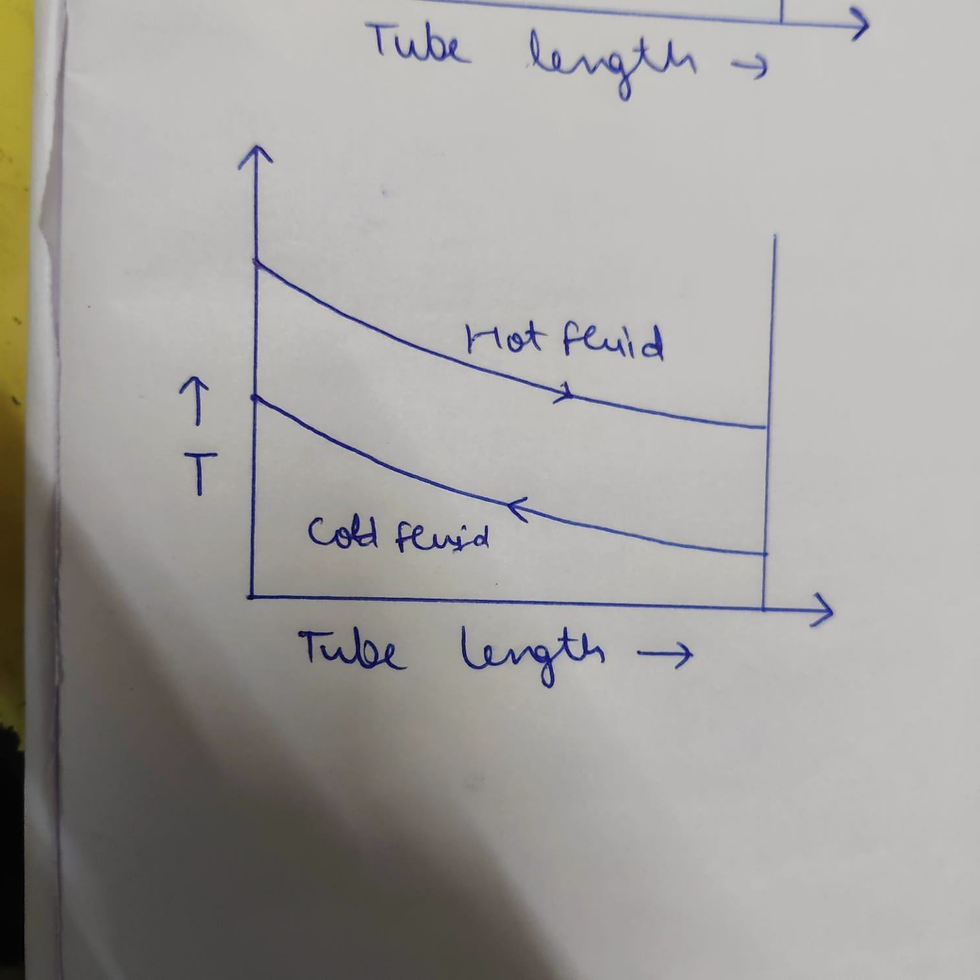
In counterflow, also known as counter-current flow, the hot fluid and the cold fluid flow in opposite directions, entering at opposite ends of the heat exchanger. The fluids travel towards each other along the heat exchange surface and exit at opposite ends.
Counterflow configuration maximizes the temperature difference between the fluids, resulting in enhanced heat transfer efficiency. As the hot fluid loses heat and the cold fluid gains heat, the temperature difference between the fluids remains relatively high along the length of the heat exchange surface.
Counterflow is advantageous when there is a significant temperature difference between the fluids or when the desired approach temperature is relatively small.
This flow pattern has more uniform temperature gradient.
Overall heat transfer is better compared to parallel flow system.
Crossflow

In crossflow, the hot fluid and the cold fluid flow at right angles to each other (90 degree out of phase), entering at opposite ends of the heat exchanger.
The choice between parallel flow and counterflow depends on factors such as
The desired temperature approach,
Available temperature difference,
Heat transfer efficiency requirements,
Specific application.
Counterflow generally offers higher heat transfer rates and greater efficiency, making it preferred when feasible. However, parallel flow may be selected when the temperature difference between the fluids is small, or if the design constraints favour that configuration.
Both parallel flow and counterflow configurations are utilized in various heat exchangers, including shell and tube heat exchangers, plate heat exchangers, and finned tube heat exchangers. The specific choice of flow configuration is determined by the specific requirements of the application, such as the desired heat transfer rate, fluid properties, and operational conditions.
Types of Heat Exchangers
Heat exchangers used in marine applications can broadly be classified into:
Tubular or Shell-and-Tube Heat Exchanger

These consist of a number of tubes enclosed within a shell. Heat is transferred through the tube walls between the fluids.
Plate Heat Exchanger

These use a series of thin, corrugated plates to create separate flow passages for the hot and cold fluids.
The two designs have different construction, maintenance requirements, pressure characteristics and applications.
Shell-and-Tube Heat Exchanger
A shell-and-tube heat exchanger consists of round tubes arranged inside a shell. One fluid flows through the tubes while the other flows around the outside of the tubes within the shell.
Heat passes through the tube walls from one fluid to the other.
Main Components
A typical shell-and-tube heat exchanger consists of:
Body/Shell
Medium A inlet and outlet cover with partition
Medium B inlet and outlet connections
End cover
Baffles
Tubes
Fixed tube plate
Floating tube plate with expansion arrangement
Why Are Baffles Provided?
Baffles perform two important functions:
They support the tubes.
They direct the shell-side fluid across the tubes.
The tubes and baffles together form what is commonly referred to as the tube stack.
Working of a Shell-and-Tube Cooler

In marine engine cooling applications, seawater has traditionally been circulated through the tubes.
The seawater comes into contact with the inside of the tubes, tube plates and water boxes, while the fluid being cooled such as lubricating oil or fresh water flows around the outside of the tubes.
Baffles guide the shell-side fluid across the tubes and provide support to the tube bundle.
A two-pass arrangement may be used, although straight-flow arrangements are also common in smaller
coolers.
Why are baffles fitted in a shell-and-tube heat exchanger?

Answer: Baffles are provided to direct the shell-side fluid across the tubes, increase the effectiveness of heat transfer and support the tubes against movement and vibration.
What is Single Pass and Two Pass in shell and tube heat exchanger?
Single-Pass: In a single-pass heat exchanger, the fluid makes only one pass through the tubes. It enters at one end of the heat exchanger, flows through the tubes, and exits at the other end. The fluid travels in a straight path through the tubes, without reversing its direction. Single-pass heat exchangers are relatively simpler in design and are commonly used when the temperature difference between the two fluids is small or when the required heat transfer rate can be achieved with a single pass.
Two-Pass: In a two-pass heat exchanger, the fluid makes two passes through the tubes. The fluid enters at one end of the heat exchanger and flows through a set of tubes, reaching the opposite end. Instead of exiting the heat exchanger, it is redirected back to the other end of the heat exchanger to make a second pass through a different set of tubes. This configuration allows the fluid to flow in a zigzag or serpentine pattern, effectively increasing the length of the flow path and the heat transfer surface area. Two-pass heat exchangers are used when a higher heat transfer rate is required or when the temperature difference between the fluids is larger.
Tube Expansion and Provision for Thermal Expansion

Temperature changes cause the tubes and shell to expand and contract.
If this thermal expansion is not properly accommodated, excessive stresses can develop in the heat exchanger.
In a shell-and-tube heat exchanger, an expansion arrangement is therefore provided. The tube stack normally has a fixed tube plate at one end and a tube plate at the other end that is free to move as the tubes expand or contract.
Synthetic rubber O-rings at the sliding tube plate allow the necessary movement.
How is thermal expansion of the tube stack accommodated in a shell-and-tube heat exchanger?
Answer: A floating/sliding tube plate is provided at one end of the tube stack. This allows the tube bundle to move as the tubes expand and contract due to temperature changes.
Materials Used in Tubular Heat Exchangers
Material selection is extremely important because marine heat exchangers are frequently exposed to seawater, which can create severe corrosion conditions.
Aluminium brass tubes have traditionally been used in marine coolers. The material mentioned in the reference material is approximately:
76% Copper + 22% Zinc + 2% Aluminium.
The successful use of such materials can depend on the formation of a protective film along the tube surface.
The shell may be made from cast iron or fabricated steel, depending on the application.
Tube Renewal in a Shell-and-Tube Heat Exchanger
Tube failure can lead to leakage and contamination between the two fluids.
When a tube is damaged beyond acceptable limits, it may need to be renewed.
General Tube Renewal Procedure
The basic procedure is:
Step 1 – Remove the Tube Flare
The flare is first removed by carefully chiseling it flush with the tube plate.
Step 2 – Split the Tube
The tube is split carefully without damaging the tube plate.
Step 3 – Remove the Tube
The tube can then be cut using a tube cutter so that the tube drops inside the shell.
Step 4 – Position the New Tube
The replacement tube is positioned correctly between the tube plates.
Step 5 – Secure and Flare
One end is secured using a brass wedge, after which the tube is flared to the required amount using a suitable flaring tool.
The flaring tool may be:
Hand-operated
Pneumatic
Motor-operated
The reference material specifies a tube protrusion of approximately 1/4 to 1/8 inch, with flaring to approximately 1/8 inch plus the tube diameter at the tip.
Important: Actual dimensions and procedures should always be verified against the manufacturer's instructions and shipboard repair procedures.
Explain the tube renewal procedure of a tubular heat exchanger.
Answer: The damaged tube is removed by removing the flare, splitting the tube carefully and cutting it with a tube cutter. A new tube is then positioned between the tube plates, secured at one end and flared using an appropriate flaring tool.
Corrosion in Tubular Heat Exchangers
Corrosion is one of the major causes of heat-exchanger deterioration.
The reference material identifies several forms of chemically induced corrosion:
General corrosion
Pitting corrosion
Stress corrosion
Dezincification
Galvanic corrosion
Crevice corrosion
Condensate grooving
Mechanical effects can also combine with corrosion and accelerate failure.
General Corrosion
General corrosion is characterized by relatively uniform metal loss over a tube, tube sheet or shell.
Aggressive conditions such as low pH in combination with carbon dioxide or oxygen can contribute to corrosion of copper-containing materials.
Proper material selection and appropriate water treatment can help extend heat-exchanger service life.
General corrosion = relatively uniform metal loss.
Pitting Corrosion

Pitting is a highly localized form of corrosion.
It develops due to electrochemical differences, often associated with variations in oxygen concentration.
A pit can become extremely dangerous because even a small number of pits can eventually penetrate the tube wall and cause leakage.
Pitting is particularly likely during shutdown periods when there is little or no flow and conditions favour the formation of concentration cells. Deposits, scratches and damage to protective surface films can increase susceptibility.
Pitting corrosion = small area, deep attack, potentially serious failure.
Stress Corrosion Cracking
Stress corrosion occurs when a susceptible material is exposed to a corrosive environment while under stress.
Heat exchanger tubes can contain residual stresses resulting from:
Tube manufacturing
Drawing
Forming U-bends
Expanding tubes into tube sheets
The resulting cracks may follow stress lines and material grain boundaries.
For stainless steel, chloride ions can contribute to stress corrosion cracking. For copper or copper-alloy tubes, ammonia can be a significant cause of stress cracking.
Dezincification

Dezincification is particularly associated with copper-zinc alloys.
In this process, zinc is selectively removed from the alloy, leaving behind a porous copper-rich structure.
The remaining material can have a sponge-like appearance.
Control methods include suitable material selection and environmental control.
Dezincification = Zinc removed from brass.
Galvanic Corrosion

Galvanic corrosion occurs when dissimilar metals are electrically connected in the presence of an electrolyte.
The less noble metal generally experiences the greater corrosion attack.
For example, when copper and steel are coupled in an electrolyte, steel can experience accelerated corrosion compared with copper.
What is galvanic corrosion?
Answer: Galvanic corrosion occurs when dissimilar metals are connected in the presence of an electrolyte, resulting in accelerated corrosion of the less noble metal.
Crevice Corrosion

Crevice corrosion occurs in concealed or poorly ventilated areas where stagnant conditions exist.
Typical locations include:
Between tubes and baffles
Under loose scale
Beneath dirt or deposits
Other shielded areas
Maintaining adequate flow velocity and preventing accumulation of solids can help control this type of corrosion.
Crevice corrosion = stagnant + hidden area.
Condensate Grooving
Condensate grooving occurs on the outside of steam-to-water heat exchanger tubes, particularly around U-bend areas.
It appears as an irregular groove or channel caused by condensate draining in rivulets.
Control of condensate pH and dissolved gases, together with cleaning of the tube bundle surface, can reduce the likelihood of this problem.
Erosion-Corrosion

Heat exchanger failure may involve both mechanical and chemical processes.
Erosion-corrosion occurs when excessive velocity, suspended solids or vibration removes protective films from the metal surface and accelerates corrosion.
It can commonly occur around:
Tube entrances
Shell inlet areas
Baffle-to-tube contact areas
U-bends
High velocity + protective film removal + corrosion = erosion-corrosion.
Corrosion-Fatigue

Corrosion-fatigue results from the combined effects of corrosion and cyclic mechanical stress.
Possible sources of cyclic stress include:
Machinery vibration
Thermal expansion and contraction
Water hammer
Repeated stresses can damage protective films and accelerate corrosion, eventually resulting in cracking or fracture.
Plate Heat Exchanger

A plate heat exchanger consists of a series of parallel plates arranged to create channels through which the fluids flow.
The hot and cold fluids pass through alternate channels, with heat being transferred through the plates.
The size of a plate can range from a few square centimeters (100 mm x 300 mm side) up to 2 or 3 square meters (1000 mm x 2500 mm side). The number of plates in a single exchanger ranges from just ten to several hundred, so reaching surface exchange areas up to thousands of square meters.

The plates are generally corrugated to:
Increase turbulence
Increase effective heat-transfer surface
Provide mechanical rigidity
Plate heat exchangers can achieve highly effective counter-current flow arrangements.
Types of Plate Heat Exchangers
Common types include:
Plate Heat Exchanger
Plates are compressed in a frame and sealed using gaskets.
Brazed Plate Heat Exchanger
Plates are furnace-brazed together without conventional gaskets.
Welded Plate Heat Exchanger
Plates are joined by welding and are suitable for applications where gasket limitations may be unsuitable.
The reference material specifically discusses PHEs and BPHEs.
Plate Heat Exchanger

In a plate-and-frame heat exchanger, plates are pressed together within a frame using headers and tie bars.
Gaskets provide sealing and also direct the fluids through their designated channels.
One of the major advantages is that the exchanger can be opened relatively quickly for inspection and cleaning.
The size of a plate can range from a few square centimeters (100 mm x 300 mm side) up to 2 or 3 square meters (1000 mm x 2500 mm side). The number of plates in a single exchanger ranges from just ten to several hundred, so reaching surface exchange areas up to thousands of square meters.
The number of plates can also be changed to modify the heat-transfer capacity.
Brazed Plate Heat Exchanger

A brazed plate heat exchanger does not use conventional headers, tie bars or sealing gaskets.
Instead, the plates are furnace-brazed together.


Copper or nickel may be used as the brazing material.
The brazed construction makes the exchanger compact, lightweight and less bulky than a gasketed arrangement.
However, a major disadvantage is that the exchanger is not readily dismantled. Therefore, maintenance and cleaning can be more difficult.
Why Are Plate Heat Exchanger Plates Corrugated?

Corrugation is one of the defining features of plate heat exchangers.
The corrugations:
Increase turbulence
Increase heat-transfer effectiveness
Increase the available heat-transfer surface
Provide mechanical rigidity
Create a tortuous flow path
The angle of the corrugation also affects the relationship between heat transfer and pressure drop.
A higher chevron angle generally produces greater turbulence and heat transfer, but also results in a higher pressure drop. A lower angle produces lower turbulence and heat transfer but reduces pressure losses.
Materials Used for Plate Heat Exchangers

Materials depend on the service conditions.
Common plate materials include:
Stainless steel
Titanium
Aluminium
For seawater applications, titanium is commonly used because of its corrosion resistance in the intended service.
Advantages of Plate Heat Exchangers
Plate heat exchangers offer several important advantages over conventional tube coolers.
Major Advantages
Compact construction
Lower weight
High heat-transfer efficiency
Easy cleaning in gasketed designs
Capacity can be increased by adding plates
High turbulence helps reduce deposits
No large dismantling space is required for certain maintenance arrangements
Flow velocity is less restricted than in some aluminium-brass tube applications
Disadvantages of Plate Heat Exchangers
Despite their advantages, plate heat exchangers also have limitations.
Major Disadvantages
Higher initial cost
Cracks and leaks in plates can be difficult to locate
Gaskets can deteriorate
Gaskets impose temperature and pressure limitations
Over-tightening can damage plates
Careful dismantling and assembly are required
Titanium plates can make the equipment expensive
What is turbulent flow?

Turbulent flow is a type of fluid flow in which the fluid particles move in an irregular and random manner, producing eddies and fluctuations in velocity and pressure.
In a heat exchanger, turbulent flow increases mixing and improves heat transfer between the fluid and the heat-transfer surface.
Shell-and-Tube vs Plate Heat Exchanger
Feature | Shell-and-Tube | Plate Heat Exchanger |
Construction | Tubes inside shell | Corrugated plates |
Compactness | Comparatively bulky | Very compact |
Heat transfer | Good | Generally high |
Cleaning | Tube cleaning required | Gasketed type is relatively easy to open |
Expansion | Floating arrangement may be provided | Different arrangement/design principles |
Capacity modification | More difficult | Plates can be added in gasketed designs |
Sealing | Tube joints and covers | Gaskets or brazing |
Maintenance | Tube bundle maintenance | Gasketed type relatively easy |
Corrosion concern | Significant in seawater service | Plate material selection is critical |
Initial cost | Application dependent | Can be high |
Describe the effect of partially closing the cooling inlet valve for shell and tube type heat exchanger.
Partially closing the cooling water inlet valve for a shell and tube type heat exchanger can have several effects on the overall heat exchanger performance and operation. The cooling water inlet valve controls the flow rate of the cooling water that enters the heat exchanger's shell side and plays a crucial role in regulating the cooling capacity and temperature control.
Here are the effects of partially closing the cooling water inlet valve:
Reduced Cooling Capacity: By partially closing the cooling water inlet valve, the flow rate of cooling water entering the tube side of the heat exchanger is reduced. This results in a decrease in the cooling capacity of the heat exchanger. As less cooling water passes through the tube side, it absorbs less heat from the shell side fluid, leading to a lower overall heat transfer rate.
Increase in Outlet Temperature: With reduced cooling water flow rate, the cooling water spends more time inside the heat exchanger, resulting in a higher outlet temperature. The cooling water's temperature will increase as it absorbs more heat from the shell side fluid over a longer residence time.
Temperature Control: Partially closing the cooling water inlet valve may have implications for temperature control in the shell side fluid. Depending on the cooling water temperature, the reduced cooling capacity may cause the tube side fluid to heat up more than desired, potentially affecting the process or system being cooled.
Risk of Fouling: Reducing the cooling water flow rate can increase the risk of fouling on the tube side of the heat exchanger. Fouling occurs when impurities in the cooling water deposit on the inner surfaces of the tubes, reducing heat transfer efficiency and potentially clogging the tubes.
Potential for Tube Damage: In extreme cases of reduced cooling water flow, there is a risk of overheating the tubes on the tube side, which can lead to tube deformation or even failure due to increased thermal stress.
It is essential to carefully adjust the cooling water flow rate based on the heat exchanger's design and the cooling requirements of the specific application. If adjustments are necessary, they should be made in consultation with qualified engineers to ensure the heat exchanger's optimal performance, avoid operational issues, and maintain the desired temperature control.
Explain how leakage is detected in shell and tube type heat exchanger.
Detecting leakage in a shell and tube type heat exchanger is crucial to prevent operational issues, potential safety hazards, and inefficient heat transfer.
Several methods are used to detect leakage in heat exchangers:
Visual Inspection: Regular visual inspections can reveal external signs of leakage, such as damp spots, rust stains, or fluid seepage around tube joints, tube plates and end covers. Any visible signs of leakage should be investigated further to identify the source and extent of the problem.
Pressure Testing: Hydrostatic or pneumatic pressure testing is a common method to detect leaks in heat exchangers. The heat exchanger is pressurized with water or air, and the pressure is monitored for a specified duration. A drop in pressure indicates the presence of a leak, which can then be localized and repaired.
Dye Penetrant Test: Dye penetrant testing involves applying a colored dye or fluorescent liquid to the suspected leak areas. The dye seeps into any cracks or openings and is then wiped off the surface. A developer is applied, causing the dye to be drawn out of the leaks, making them visible under UV light or in visible light, depending on the type of dye used.
Ultrasonic Testing: Ultrasonic testing utilizes high-frequency sound waves to detect internal leaks, cracks, or flaws. Ultrasonic probes are used to send and receive sound waves through the material. Any changes in the transmitted sound waves indicate the presence of defects, including leaks.
Acoustic Monitoring: Acoustic emission monitoring involves using sensitive microphones or sensors to detect sound emissions from leak points. As the fluid escapes from the leak, it generates acoustic signals that can be detected and analyzed to identify the location of the leak.
Thermal Imaging: Thermal imaging cameras can be used to identify temperature variations caused by leaking fluids. A leaking fluid may have a different thermal signature compared to the surrounding components, allowing for the identification of potential leakage points.
Tracer Gases: In some cases, a tracer gas, such as helium, is introduced into the heat exchanger, and detectors are used to identify its presence in areas where leakage may be occurring.
It is essential to conduct routine inspections and testing to promptly identify and address any leakage issues in heat exchangers. Early detection and timely repairs can prevent further damage, improve safety, and ensure optimal heat exchanger performance. Regular maintenance and adherence to recommended inspection schedules are vital for the reliable and efficient operation of shell and tube heat exchangers.
Important MEO Class 4 Questions
What is a heat exchanger?
A device that transfers heat through a conducting wall from one fluid to another.
What are the main types of heat exchangers?
Tubular/shell-and-tube and plate heat exchangers.
What is the function of baffles?
To direct shell-side fluid across the tubes and support the tube bundle.
Why is an expansion arrangement provided?
To accommodate thermal expansion and contraction of the tube stack.
Name the types of corrosion found in tubular heat exchangers.
General, pitting, stress corrosion, dezincification, galvanic, crevice and condensate-grooving corrosion.
What is dezincification?
Selective removal of zinc from a copper-zinc alloy.
What is galvanic corrosion?
Corrosion caused by coupling dissimilar metals in the presence of an electrolyte.
Why are plate heat exchanger plates corrugated?
To increase turbulence, heat-transfer surface and mechanical rigidity.
What are the advantages of a plate heat exchanger?
It is compact, lightweight, efficient, relatively easy to clean in gasketed designs and can have its capacity modified by adding plates.
What are the disadvantages?
High initial cost, possible difficulty locating leaks, gasket limitations, careful assembly requirements and susceptibility to damage from over-tightening.
Frequently Asked Questions (FAQ)
What is the main purpose of a marine heat exchanger?
Its primary purpose is to transfer heat between two fluids while keeping them separated by a conducting surface.
What is the difference between a shell-and-tube and plate heat exchanger?
A shell-and-tube exchanger transfers heat through tubes enclosed within a shell, whereas a plate exchanger uses a series of corrugated plates that form separate flow channels.
Why are baffles used in shell-and-tube heat exchangers?
Baffles direct fluid across the tubes and support the tube bundle, improving the heat-transfer arrangement.
Why is thermal expansion important in a heat exchanger?
Different temperatures cause the tubes and other components to expand and contract. An appropriate expansion arrangement prevents excessive thermal stresses.
What is the most dangerous feature of pitting corrosion?
Although the affected area may be small, pits can penetrate deeply and eventually cause tube leakage or failure.
What causes galvanic corrosion?
It occurs when dissimilar metals are electrically connected in the presence of an electrolyte.
Why is titanium used in seawater plate heat exchangers?
Titanium is used because of its suitability for seawater service and strong corrosion resistance in the intended application.
What is the main advantage of a gasketed plate heat exchanger?
It can be opened relatively easily for inspection and cleaning, and its capacity can be modified by changing the number of plates.
What is the major disadvantage of a brazed plate heat exchanger?
It is not readily dismantled, making internal cleaning and maintenance difficult.
Why are heat exchangers important for marine engineers?
They are essential for maintaining operating temperatures of critical systems such as engine cooling water and lubricating oil, directly contributing to reliable and efficient machinery operation.