Electrical Motors on Ships: Complete Guide to AC & DC Motors | Everything You Need to Know


Electrical motors are among the most important machines found onboard a modern ship. From pumps and fans to cranes, winches, windlasses, steering systems and other auxiliary machinery, electric motors provide the mechanical power required for reliable shipboard operation.
For marine engineering students, cadets and engineers preparing for IMU examinations, competency examinations, oral examinations and technical interviews, understanding the construction, working principle, types, characteristics and applications of electrical motors is essential.
This guide explains AC and DC motors used in marine applications in simple and easy-to-remember language. It covers induction motors, rotating magnetic fields, squirrel-cage and slip-ring rotors, slip, motor enclosures, motor name plates, DC motor construction, back EMF, speed equations, DC motor types and motor characteristics.
What Is an Electrical Motor?
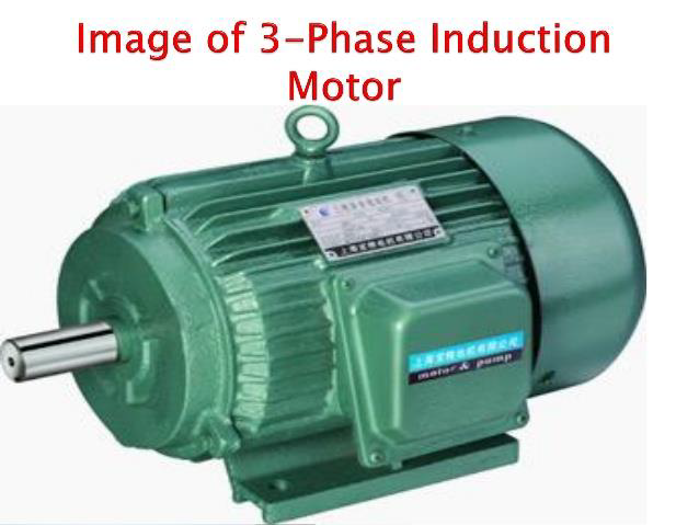
An electrical motor is a machine that converts electrical energy into mechanical energy.
The mechanical output from a motor is normally used to drive another machine such as a pump, fan, compressor, crane, winch or other rotating equipment.
Electrical motors used onboard ships can broadly be classified into:
AC motors
DC motors
Three-phase AC induction motors are particularly important because of their simple construction, reliability and relatively low maintenance requirements.
AC Electrical Motors Used on Ships
A three-phase induction motor operates from a three-phase AC supply and is commonly used for heavier loads.
The two important types of three-phase induction motors are:
Squirrel-cage induction motor
Slip-ring or wound-rotor induction motor
Because of their rugged construction and reliability, induction motors have many applications in marine machinery.
Applications of Induction Motors on Ships
Induction motors are commonly associated with equipment such as:
Pumps
Fans
Blowers
Ballast pumps
Fire pumps
Freshwater pumps
Seawater pumps
Engine auxiliary pumps
Exhaust fans
Winches
Windlasses
Lifts
Cranes
Other auxiliary machinery
The source material also identifies applications such as propulsion, deck machinery and blowers with different motor types.
Why Are Induction Motors Popular on Ships?
Three-phase induction motors have several important advantages:
Simple and rugged construction
High reliability
Relatively low cost
Good efficiency
Good power factor
Low maintenance requirements
Self-starting operation
Their major limitation is that motor speed changes with load, and speed control can require additional equipment or reduced efficiency depending on the method used.
Easy Exam Memory Trick
Induction Motor = Simple + Strong + Reliable + Self-starting
Rotating Magnetic Field in a Three-Phase Induction Motor
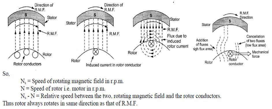
The rotating magnetic field (RMF) is one of the most important concepts in an induction motor.
When a three-phase AC supply is connected to the stator windings, the three phase currents produce a magnetic field that continuously rotates around the stator.
The stator windings are distributed around the stator and are separated by approximately 120° electrical/space relationship, producing a rotating magnetic field.
The magnetic field rotates at synchronous speed.
The synchronous speed is:
Ns = 120f / P
Where:
Ns = synchronous speed in rpm
f = supply frequency in Hz
P = number of poles
Why Does an Induction Motor Never Run at Synchronous Speed?
This is a very common examination question.
The rotor must have relative motion with respect to the rotating magnetic field for EMF and rotor current to be induced.
If the rotor reached synchronous speed:
Ns − N = 0
Therefore, there would be no relative motion between the rotor and rotating magnetic field.
As a result:
No relative motion → No induced EMF → No rotor current → No torque
Therefore, the rotor cannot continuously operate at synchronous speed.
It always runs slightly below synchronous speed and is therefore called an asynchronous motor or sub-synchronous motor.
Exam Point
Induction motor = Rotor speed is always slightly less than synchronous speed.
Construction of a Three-Phase Induction Motor
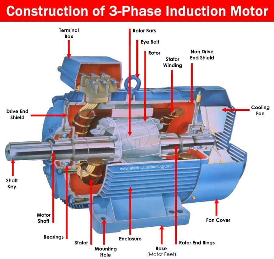
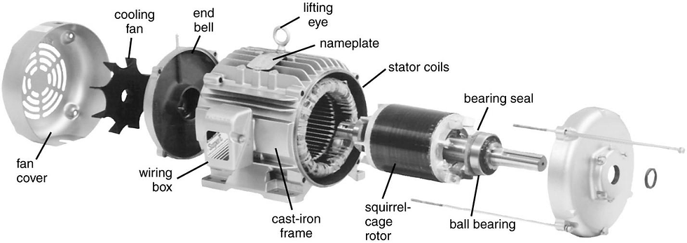
A three-phase induction motor mainly consists of:
Stator
Rotor
Air gap
The stator and rotor are separated by a small air gap. The source notes an approximate air-gap range of 0.4 mm to 4 mm, depending on motor power.
Stator of an Induction Motor
The stator is the stationary part of the motor.
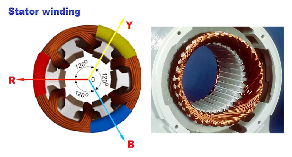
It generally consists of:
Outer steel frame
Laminated magnetic core
Slots
Three-phase insulated windings
The core is made from thin laminations to reduce hysteresis and eddy-current losses.
The stator winding is placed in slots and may be connected in star or delta, depending on the motor design and supply requirements.
The number of poles determines the approximate synchronous speed.
Important Relationship
More poles → Lower speed
Fewer poles → Higher speed
When the three-phase supply is applied, the stator produces the rotating magnetic field that induces current in the rotor.
Rotor of an Induction Motor
The rotor is the rotating part of the induction motor.
It consists of a laminated core mounted on a shaft. Depending on its construction, the rotor can be:
Squirrel-cage rotor
Wound or slip-ring rotor
Squirrel-Cage Rotor
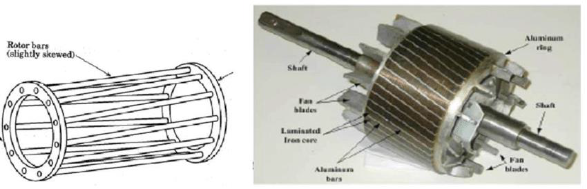
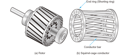
A squirrel-cage rotor consists of conducting bars placed in slots around the rotor core.
These bars are permanently short-circuited by end rings.
The rotor does not have an electrical connection to the external supply. Instead, current is induced in the rotor by electromagnetic induction from the stator.
Main Features of a Squirrel-Cage Rotor
Simple construction
Rugged design
No brushes
No slip rings
Low maintenance
Reliable operation
High efficiency
External rotor resistance cannot be added
Starting torque is comparatively limited
The source material identifies squirrel-cage motors as the most widely used induction-motor type because of their simple and robust construction.
Easy Memory Trick
Squirrel Cage = Simple + Strong + Short-circuited
Slip-Ring or Wound-Rotor Induction Motor
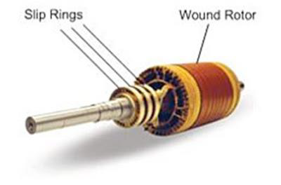
A wound-rotor induction motor has a three-phase winding on its rotor.
The winding ends are connected to three insulated slip rings mounted on the rotor shaft. Brushes connect the slip rings to an external resistance arrangement.
External resistance can be introduced into the rotor circuit during starting.
This provides better control of starting torque.
As the motor accelerates, the external resistance is progressively reduced. At normal operating speed, the rotor circuit can be short-circuited.
Squirrel-Cage vs Slip-Ring Induction Motor
Feature | Squirrel-Cage Motor | Slip-Ring Motor |
Rotor construction | Conducting bars and end rings | Three-phase wound rotor |
Construction | Simple | More complicated |
Slip rings | Not present | Present |
Brushes | Not present | Present |
External resistance | Cannot be added | Can be added |
Starting torque | Moderate | High starting torque possible |
Maintenance | Low | Higher |
Cost | Lower | Higher |
Speed control | Limited | Rotor-resistance control possible |
Rotor copper losses | Lower | Higher |
Typical applications | Pumps, fans, blowers, grinders | Cranes, lifts, hoists and similar high-starting-torque duties |
These differences are central to understanding why the two rotor designs are selected for different duties.
One-Line Exam Answer
Squirrel cage = rugged and low maintenance.
Slip ring = high starting torque and external resistance control.
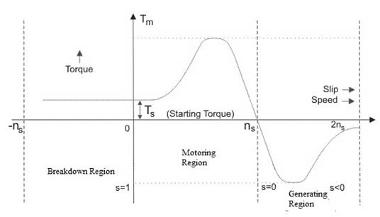
Slip in an Induction Motor
Slip is the difference between synchronous speed and actual rotor speed, expressed relative to synchronous speed.
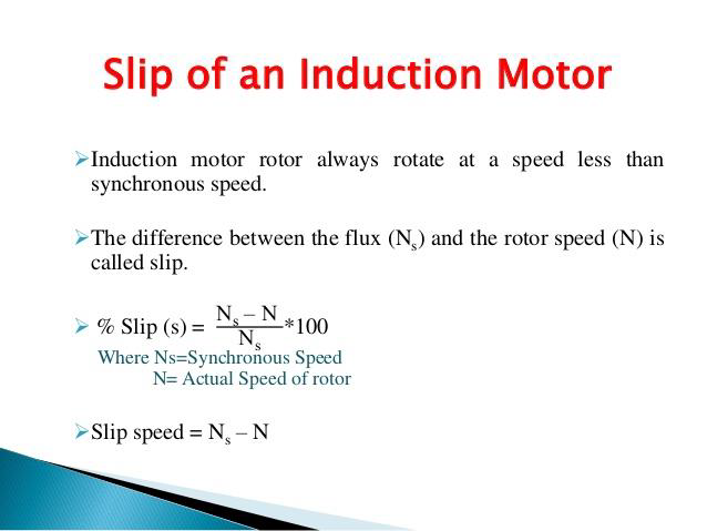
The formula is:
s = (Ns − N) / Ns
If expressed as a percentage:
Slip % = [(Ns − N) / Ns] × 100
Where:
Ns = synchronous speed
N = rotor speed
Slip is necessary because the relative motion between the rotating magnetic field and rotor is required to induce rotor EMF and current.
What Happens at Different Slip Values?
Slip = 0
Rotor speed equals synchronous speed. There is no relative motion, so no rotor EMF or torque is induced. Therefore, an induction motor cannot operate normally with zero slip.
Slip = 1
The rotor is stationary. This is the starting or standstill condition.
Negative Slip
If the rotor is driven above synchronous speed, the machine can operate in the generating region.
Slip Greater Than 1
Under the plugging/braking condition described in the source material, the rotor rotates opposite to the rotating magnetic field and the machine develops braking action.
Rotor Frequency
The rotor frequency is related to slip by:
fr = s × f
Where:
fr = rotor frequency
s = slip
f = supply frequency
Example
Suppose:
Supply frequency = 50 Hz
Slip = 0.04
Then:
fr = 0.04 × 50
fr = 2 Hz
This type of relationship is commonly used in induction-motor numerical problems.
Motor Enclosures and Cooling
Motor enclosures protect electrical motors from environmental conditions such as:
Water
Moisture
Dust
Corrosive substances
Foreign objects
The enclosure also influences the method of motor cooling.
Drip-Proof Open Ventilated Motor
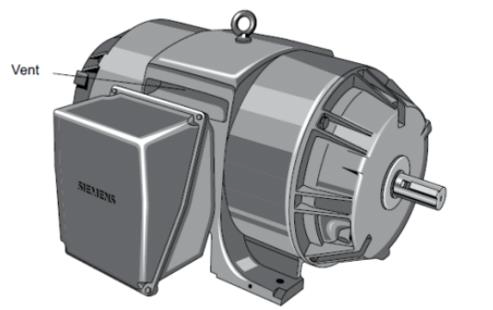
This type allows ventilation while providing protection against dripping liquids.
Air is drawn into the motor for cooling, while mesh screens help prevent foreign objects from entering.
The screens must remain clean because blocked ventilation can result in overheating.
Totally Enclosed Non-Ventilated Motor — TENV
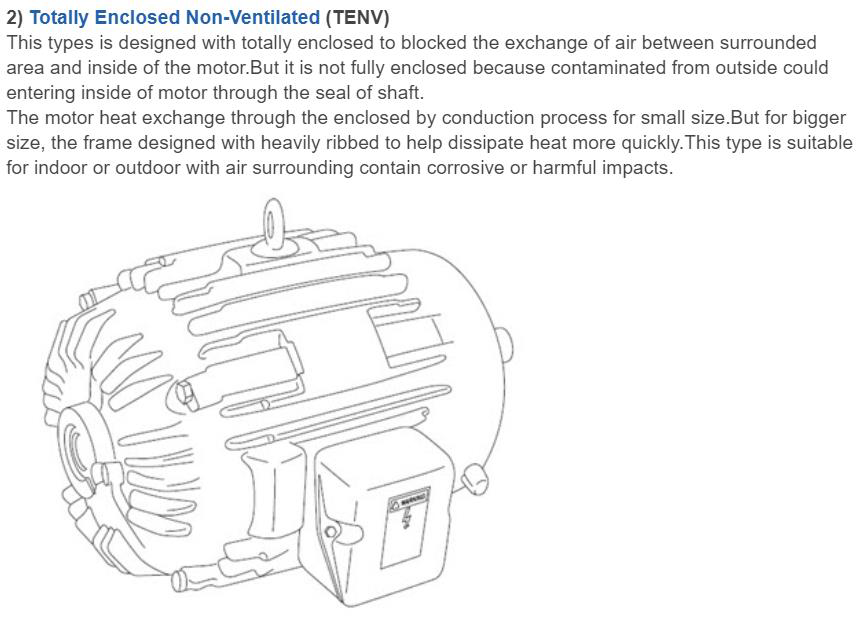
A TENV motor is fully enclosed and does not exchange air directly with the surrounding atmosphere.
Heat is dissipated through the motor body, often assisted by external ribs.
It can be used in environments where protection from contamination is important.
Totally Enclosed Fan-Cooled Motor — TEFC
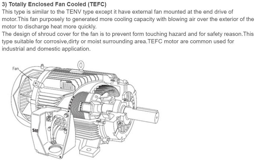
A TEFC motor is enclosed and uses an external fan to move air over the outside of the motor casing.
This provides improved cooling while maintaining protection from the surrounding environment.
Explosion-Proof or Flameproof Motor
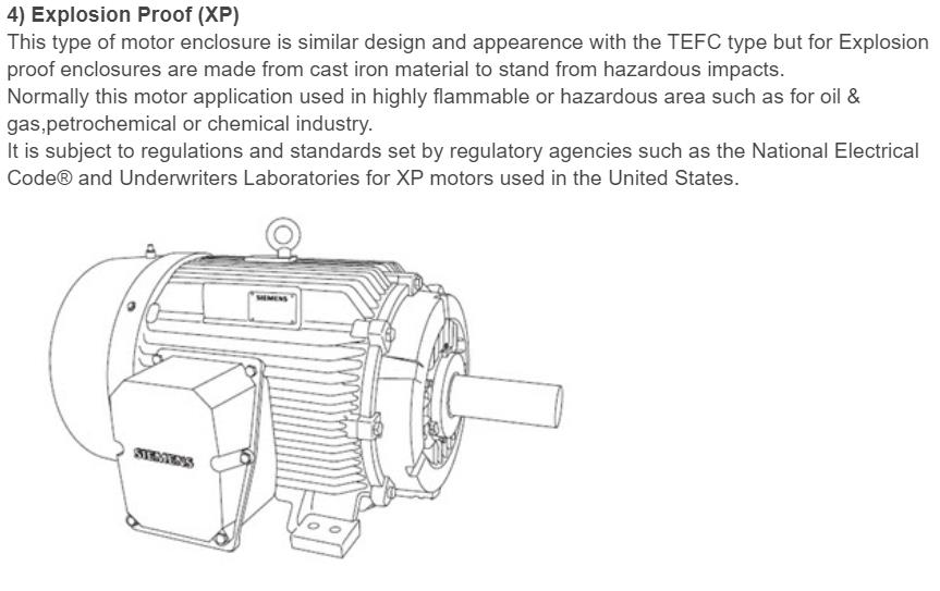
These motors are designed for hazardous environments where flammable gases or vapours may be present.
They are associated with applications such as oil, gas, petrochemical and chemical installations.
Deck Watertight Motor
Deck watertight motors are designed to protect against water ingress and are suitable for machinery located in exposed deck areas where sea spray and weather conditions can be encountered.
How to Read a Motor Name Plate
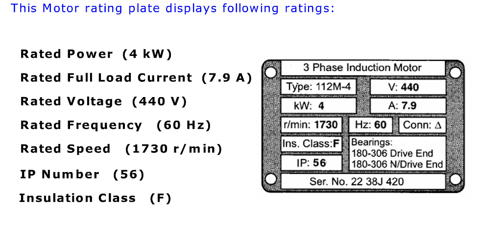
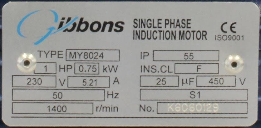
A motor name plate provides important information required for the correct operation of the motor.
For marine engineers, understanding every name-plate parameter is extremely important.
Typical information includes:
Rated Power
The rated power is the mechanical shaft output that the motor can provide under its specified operating conditions.
Example:
4 kW
Rated Full-Load Current
The full-load current indicates the current associated with rated motor operation.
Example:
7.9 A
Rated Voltage
This is the voltage for which the motor is designed.
Example:
440 V
Operating a motor at an unsuitable voltage can result in overheating, poor performance or damage.
Rated Frequency
The rated frequency specifies the supply frequency for which the motor is designed.
Example:
50 Hz or 60 Hz
Rated Speed
The rated speed is the motor's approximate operating speed under rated load.
Example:
1730 rpm
IP Rating
The IP rating indicates the degree of protection provided by the enclosure against ingress of solid objects and moisture.
Example:
IP56
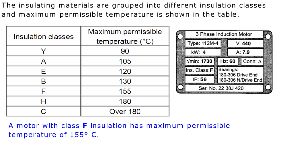
Insulation Class
The insulation class indicates the thermal capability of the winding insulation.
Example:
Class F
Connection
The name plate can also indicate whether the motor windings are connected in:
Star
Delta
The source material identifies these as important name-plate parameters for a three-phase induction motor.
Exam Memory Trick
Remember:
Power – Current – Voltage – Frequency – Speed – IP – Insulation – Connection
Speed and Torque Characteristics of an Induction Motor
An induction motor is generally considered a constant-speed machine because its speed changes only slightly between no-load and full-load conditions.
As the mechanical load increases:
Load increases → Rotor current increases → Torque increases
The motor develops sufficient torque to meet the mechanical load demand.
DC Motors Used in Marine Engineering
What Is a DC Motor?
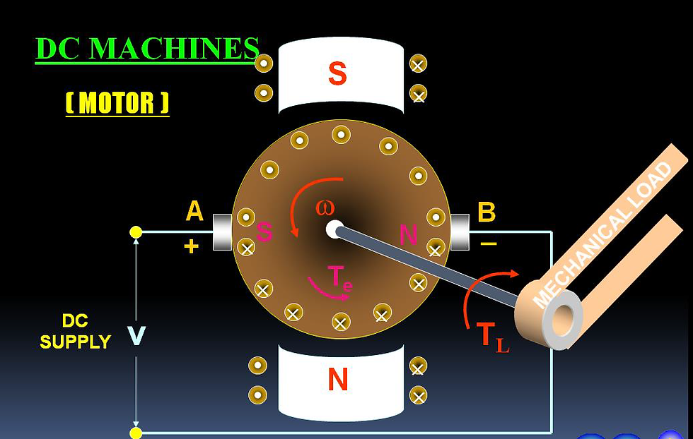
A DC motor converts direct-current electrical energy into mechanical energy.
DC motors are classified according to how their field winding is supplied or excited.
Construction of a DC Motor
The main components of a DC motor include:
Yoke
The yoke forms the outer body of the machine.
It provides mechanical support and forms part of the magnetic circuit.
Field Core and Field Winding
The field winding produces the main magnetic field required for motor operation.
Armature
The armature is the rotating part of the DC machine.
Commutator
The commutator performs the switching function associated with the armature winding and allows the machine to provide DC at the brushes.
Brushes and Brush Holders
Brushes provide electrical contact between the rotating commutator and the external circuit.
Shaft, Bearings and End Housing
These components provide mechanical support and allow the rotating assembly to transmit mechanical power.
Back EMF in a DC Motor
When a DC motor rotates, the armature conductors cut magnetic flux and an EMF is induced.
This induced EMF opposes the applied supply voltage and is therefore called back EMF (Eb).
The basic voltage equation is:
V = Eb + IaRa
Where:
V = supply voltage
Eb = back EMF
Ia = armature current
Ra = armature resistance
Back EMF is an important concept because it controls the armature current during normal motor operation.
Easy Exam Memory
Applied voltage = Back EMF + Armature voltage drop
DC Motor Speed Equation
The back EMF of a DC motor is:
Eb = PΦZN / 60A
Also:
Eb = V − IaRa
Combining these equations:
N = (V − IaRa) / KΦ
Where:
K = PZ / 60A
This equation provides the fundamental relationship between motor speed, applied voltage, armature current, armature resistance and magnetic flux.
What Does the Speed Equation Tell Us?
Motor speed:
Increases when supply voltage increases
Decreases when field flux increases
Can be controlled by changing voltage
Can be controlled by changing field flux
Can also be influenced by armature resistance
In simple form:
N ∝ V
and
N ∝ 1/Φ
Therefore:
Higher voltage → Higher speed
Higher flux → Lower speed
Types of DC Motors
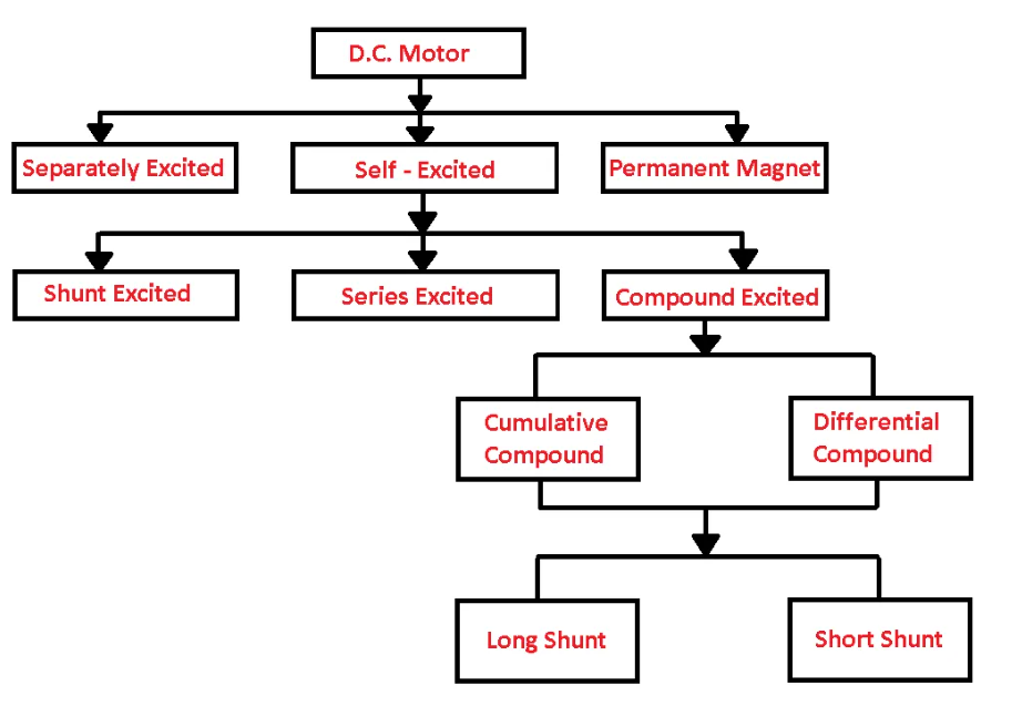
DC motors can be classified according to their method of field excitation.
The main types are:
Permanent-magnet motor
Separately excited motor
Shunt motor
Series motor
Compound motor
The self-excited category includes shunt, series and compound motors.
Separately Excited DC Motor
In a separately excited motor, the field winding is supplied from an independent source.
The field current is:
If = V / Rf
The field is therefore independently controlled from the armature circuit.
DC Shunt Motor
In a shunt motor, the field winding is connected in parallel with the armature.
Because the field winding is connected across the supply, the field flux remains approximately constant under normal conditions.
As a result, a DC shunt motor has relatively constant-speed characteristics.
Applications
Applications mentioned in the source include:
Wipers
Automatic windscreens
Conveyors
Fans
Boring machines
Shapers
Blowers
Spinning and weaving machines
Centrifugal pumps
Exam Memory
Shunt motor = Parallel field = Nearly constant speed
DC Series Motor
In a series motor, the field winding is connected in series with the armature.
Therefore:
If = Ia = IL
The series field carries the full armature current and is designed using thick wire with comparatively fewer turns.
Before magnetic saturation, flux is approximately proportional to armature current.
Why Does a Series Motor Have High Starting Torque?
The torque equation is:
T = KΦIa
Before saturation:
Φ ∝ Ia
Therefore:
T ∝ Ia²
This gives the DC series motor very high starting torque.
Applications
Series motors are suitable for applications requiring high starting torque, such as:
Cranes
Lifts
Elevators
Winches
Electric traction
Air compressors
Power tools
Other high-starting-torque applications
Most Important Exam Question
Why should a DC series motor never be run without load?
At no load, armature current becomes very small.
Therefore the series field flux also becomes very small.
Since speed is inversely related to flux:
Low flux → Very high speed
This can result in dangerous overspeed and mechanical damage.
Therefore:
Never run a DC series motor without load.
DC Compound Motor
A compound motor contains both:
Shunt field winding
Series field winding
It therefore combines characteristics of shunt and series motors.
Compound motors can be classified according to the connection of the shunt winding.
Short-Shunt Compound Motor
In a short-shunt arrangement, the shunt field is connected across the armature only.
The source gives:
Ise = IL = Ia + Ish
and:
V = Eb + IaRa + IseRse
Long-Shunt Compound Motor
In a long-shunt arrangement, the shunt field is connected across the combination of armature and series field.
The source gives:
Ise = Ia
and:
IL = Ia + Ish
with:
V = E + IaRa + IseRse
Cumulative and Differential Compound Motors
Compound motors can also be classified according to the relationship between the shunt and series magnetic fields.
Cumulative Compound Motor
In a cumulative compound motor, the series-field flux adds to the shunt-field flux.
Therefore:
Φ = Φsh + Φse
This produces:
High starting torque
Better speed regulation
Good performance under varying loads
Applications include:
Presses
Electric shovels
Conveyors
Stamping machines
Elevators
Compressors
Rolling mills
Heavy planers
Differential Compound Motor
In a differential compound motor, the series field opposes the shunt field.
Therefore:
Φ = Φsh − Φse
This produces undesirable torque and speed characteristics, and such motors are rarely used in practical applications.
Easy Memory Trick
Cumulative = Fields Combine
Differential = Fields Diminish
Characteristics of DC Motors
Three important DC motor characteristics are frequently studied:
Speed vs Armature Current
Torque vs Armature Current
Speed vs Torque
The fundamental torque equation is:
T = KtΦIa
For a shunt motor, where flux remains approximately constant:
T ∝ Ia
Therefore, torque increases approximately linearly with armature current under constant-flux conditions.
Shunt Motor Characteristics
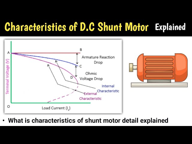
A shunt motor provides:
Nearly constant speed
Moderate starting torque
Good suitability for constant-speed loads
Series Motor Characteristics
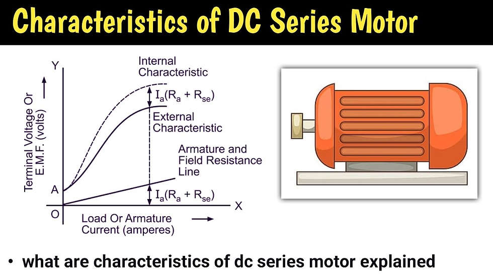
A series motor provides:
Very high starting torque
Significant speed variation with load
Dangerously high speed under no-load conditions
This makes it suitable for traction, cranes, hoists and similar applications requiring high starting torque.
Cumulative Compound Motor Characteristics
A cumulative compound motor provides:
High starting torque
Better speed regulation than a series motor
Ability to handle sudden heavy loads
Differential Compound Motor Characteristics
A differential compound motor has comparatively poor torque characteristics and is rarely used in practical applications.
AC Motor vs DC Motor
Feature | AC Induction Motor | DC Motor |
Supply | AC | DC |
Main magnetic principle | Rotating magnetic field | Electromagnetic interaction |
Main rotating component | Rotor | Armature |
Commutator | Not required | Required in conventional DC machines |
Brushes | Not required in squirrel-cage motor | Used with commutator |
Maintenance | Generally low | Generally higher |
Speed control | Often requires dedicated control equipment | Can be controlled through voltage, flux or resistance |
Common characteristic | Rugged and reliable | Different characteristics depending on motor type |
Common Viva Questions on Electrical Motors
Why does an induction motor require slip?
Slip provides the relative motion required between the rotating magnetic field and rotor so that rotor EMF and rotor current can be induced.
Why can a squirrel-cage motor not use external rotor resistance?
Its rotor bars are permanently short-circuited by end rings, so an external resistance cannot be inserted into the rotor circuit.
Why is a slip-ring motor used when high starting torque is required?
External resistance can be introduced into the rotor circuit during starting, allowing high starting torque to be obtained.
What happens if an induction motor reaches synchronous speed?
Relative motion between the rotor and rotating magnetic field becomes zero. Rotor EMF and current disappear, and therefore torque disappears.
What is the difference between synchronous speed and rotor speed?
Synchronous speed is the speed of the rotating magnetic field, while rotor speed is the actual mechanical speed of the rotor. In an induction motor, rotor speed remains slightly below synchronous speed during normal motoring operation.
What is back EMF?
Back EMF is the EMF induced in the rotating armature of a DC motor that opposes the applied supply voltage.
Why does a DC series motor have high starting torque?
Before saturation, its flux increases approximately with armature current. Since torque is proportional to flux multiplied by armature current, torque can approximately vary as the square of armature current.
Why should a DC series motor not be operated without load?
At no load, armature current and series-field flux become very small, causing the motor speed to rise to a potentially dangerous level.
What is the function of a commutator in a DC motor?
The commutator performs the required switching of armature connections so that the motor develops continuous torque in one direction.
What does IP56 mean on a motor name plate?
The IP marking identifies the degree of protection provided by the enclosure against ingress of solid objects and water.