Air Compressor: Working Principle, Types, Applications, Construction, Safety Devices and Maintenance

An air compressor is an important auxiliary machine in a ship’s engine room. It takes atmospheric air, compresses it, and increases its pressure. Compressed air is mainly used for starting the main and auxiliary engines, operating control and automation systems, pneumatic tools, and other shipboard services.
The compressed air stores energy, which is released when needed to perform useful work. Therefore, a reliable air compressor is essential for the safe and smooth operation of a ship.
What is an Air Compressor?

An air compressor produces pressurized air by decreasing the volume of air and consequently increasing its pressure.
In technical terms:
An air compressor is a mechanical device in which mechanical or electrical energy is converted into pressure energy in the form of compressed air.
The compressor operates according to thermodynamic principles. When the volume occupied by air is reduced, its pressure increases. During actual compression, the temperature of the air also increases.
When compressed air is stored in an air receiver, it acts as a reservoir of energy. Whenever a system requires air, the stored compressed air can be supplied through the appropriate pipeline.
Why is Compressed Air Important on Ships?

A modern vessel has numerous systems that require compressed air. Depending on the pressure and quality required, compressed air can be divided into different services.
The major applications on board include:
Main Engine Starting
One of the most important applications of compressed air is starting the main engine.
Large marine diesel engines generally use high-pressure starting air. The compressed air is supplied from the starting-air receivers to the engine starting system, where it acts on the starting arrangement to rotate the engine until it reaches sufficient speed for fuel injection and combustion.
Starting-air pressure may typically be in the range of 24–42 bar, depending on the ship and system design.
Auxiliary Engine Starting
Compressed air is also used for starting auxiliary engines where an air-starting arrangement is provided.
Control and Automation Air
Compressed air is used for control and automation systems associated with main and auxiliary machinery.
Control air is typically supplied at a lower pressure, with the material indicating approximately 7 bar for control air.
Service Air
Service air is used for general shipboard requirements and is also typically around 7 bar, with reducing valves used where individual equipment requires a different pressure.
Pneumatic Tools
Compressed air can operate pneumatic tools used for:
Chipping
Drilling
Buffing
Cleaning
Machinery overhauling
Other workshop operations
Pneumatic tools are particularly useful in marine engineering because they eliminate the need for an electric motor at the point of operation.
Pressure Testing
Compressed air can be used in pressure-testing applications involving machinery components and pipelines, subject to the applicable safety procedures and testing requirements.
Ship's Whistle and Fog Horn
Compressed air is also used for operating the ship's whistle and fog horn.
Lifeboat Applications
Where an air motor is fitted as part of a lifeboat heaving arrangement, compressed air may be used to operate it.
Hydrophore System
Compressed air is used in the hydrophore system to maintain pressure and supply water to accommodation spaces and other parts of the vessel.
Spray Painting
Compressed air is used for pressurized spray-painting systems.
Soot Blowing
Boilers and economizers may use compressed air for soot blowing and cleaning applications.
Pneumatic Pumps
Portable pneumatic pumps can be used for transferring oil, water and bilge fluids.
General Cleaning
Service compressed air can also be used for general cleaning and other shipboard services.
Different Types of Air Compressors
The training material identifies four main types of air compressors:
Centrifugal compressor
Rotary vane compressor
Rotary screw compressor
Reciprocating air compressor
These compressors operate on different principles and are selected according to the required pressure, capacity and application.
Centrifugal Compressor

A centrifugal compressor is a dynamic compressor. It uses the high-speed rotation of an impeller to increase the velocity of the incoming air.
The air enters the rotating impeller and gains kinetic energy. This velocity energy is subsequently converted into pressure energy.
Centrifugal compressors are generally suitable where large volumes of air at relatively continuous flow are required.
Rotary Vane Compressor

A rotary vane compressor uses a rotating rotor fitted with sliding vanes.
As the rotor turns, the vanes form chambers of varying volume. Air is trapped within these chambers and compressed as the available volume decreases.
The rotary vane arrangement provides a continuous delivery of compressed air.

Rotary Screw Compressor

A rotary screw compressor uses rotating screw elements to compress air.
Air enters the compressor and becomes trapped between the rotating screw profiles. As the rotors rotate, the volume of the trapped air decreases and its pressure increases.
Rotary screw compressors are commonly associated with continuous compressed-air requirements because they can provide relatively smooth air delivery.

Reciprocating Air Compressor

The reciprocating compressor is particularly important in marine engineering.
It uses a piston moving inside a cylinder to compress air. The movement of the piston reduces the volume of air trapped inside the cylinder and increases its pressure.
Air flow is controlled using suction and discharge valves.
The training material specifically notes that reciprocating compressors are used in marine diesel-engine plants for starting air and other control systems. Because the delivery is pulsating, air reservoirs are required to provide a stored supply and smooth the demand.
Working Principle of a Reciprocating Air Compressor
The working principle can be understood through the movement of the piston.

Suction Stroke
During the suction stroke, the piston moves away from the cylinder head.
The pressure inside the cylinder falls below the suction-line pressure, allowing atmospheric air to enter through the suction valve.
Compression Stroke
The piston then moves toward the cylinder head.
The suction valve closes and the trapped air is compressed.
As the piston reduces the volume of the air, its pressure increases. At the same time, the temperature of the air also increases.
Delivery Stroke
When the cylinder pressure becomes sufficiently higher than the delivery pressure, the discharge valve opens.
The compressed air leaves the cylinder and flows toward the next stage or air receiver.
The cycle then repeats.
Thermodynamics of Air Compression

Understanding the thermodynamics of compression is essential for marine engineering students.
Atmospheric Pressure
At sea level, atmospheric pressure is approximately:
14.7 psi ≈ 1 bar
Atmospheric pressure is measured using a barometer.
Gauge Pressure
Gauge pressure represents pressure above atmospheric pressure.
Most ordinary pressure gauges indicate gauge pressure rather than absolute pressure.
Types of Compression Processes
There are three important compression processes to remember.
Isothermal Compression
In an isothermal compression process, the temperature remains constant.
If the heat generated during compression is continuously removed so that the temperature remains constant, the process is considered isothermal.
The relationship is:
PV = C
Isothermal compression represents a theoretical process requiring comparatively low work.
Adiabatic Compression
In adiabatic compression, no heat is removed from the system.
The heat generated during compression remains within the air.
Consequently, the air temperature rises significantly.
Polytropic Compression
Actual compressor operation generally falls somewhere between ideal isothermal and adiabatic compression.
When some heat is removed during compression, but not enough to maintain constant temperature, the process is called polytropic compression.
Why Are Marine Air Compressors Usually Multi-Stage?
A very important question for marine engineering examinations is:
Why is air compressed in two or three stages instead of one stage?

The main reason is efficient compression and temperature control.
The number of stages depends on the required final pressure. As the required pressure increases, more stages may be required.
Consider compressing air from a low initial pressure to a very high final pressure in a single cylinder.
The temperature would rise considerably, creating several problems:
Increased lubrication difficulties
Higher discharge temperatures
Greater possibility of oil carbonization
Increased risk of deposits around valves
Greater mechanical and thermal stresses
Higher work requirement
Instead, the compression is divided into stages.
After each stage, the compressed air is cooled in an intercooler before entering the next stage.
This reduces the temperature and brings the actual compression process closer to the ideal isothermal process.
Advantages of Multi-Stage Compression
Multi-stage compression provides several important advantages.
Higher Volumetric Efficiency
Multi-stage arrangements can improve the volumetric efficiency of the compressor.
Lower Power Requirement
The work required for compression is reduced, resulting in lower power consumption.
Better Cylinder Design
The size and strength of individual cylinders can be designed according to the volume and pressure handled by each stage.
Better Mechanical Balance
Multi-cylinder compressors provide more uniform torque and better mechanical balance, reducing the flywheel requirement.
Lower Compression Temperature
Intercooling significantly reduces the maximum temperature reached during compression.
This helps reduce lubrication problems and explosion hazards.
Reduced Leakage Losses
Multi-stage compression can also reduce leakage losses.
What is an Intercooler?

An intercooler is a heat exchanger installed between compressor stages.
When air leaves the low-pressure stage, it is hot because compression has increased its temperature.
The air is passed through an intercooler where heat is removed, normally by cooling water.
The cooled air then enters the next compression stage.
This process:
Reduces air temperature
Reduces compression work
Improves efficiency
Protects lubrication
Reduces carbon formation
Helps protect valves
The training material emphasizes that cooling between stages lowers the work required for compression and helps prevent mechanical problems caused by uncontrolled air temperature.
Two-Stage Air Compressor
A typical marine starting-air compressor may use two stages.
In a two-stage compressor:
Atmospheric Air → LP Stage → Intercooler → HP Stage → Aftercooler → Air Receiver
The low-pressure piston is larger because it handles a larger volume of air.
The high-pressure piston is smaller because the air volume has already been reduced during the first stage.
A two-stage single-crank arrangement may have two pistons of different dimensions mounted in tandem.
One advantage of this arrangement is that any leakage toward the crankcase is at lower pressure and temperature, reducing the risk of an explosion in the crankcase.
Intercooler and Aftercooler
These two components are frequently confused.
Intercooler

The intercooler is installed between compressor stages.
Its purpose is to cool the air before it enters the next compression stage.
Aftercooler

The aftercooler is installed after the final compression stage.
Its purpose is to cool the final compressed air before it enters the air receiver or downstream system.
A typical arrangement therefore looks like:
Air Intake → LP Cylinder → Intercooler → HP Cylinder → Aftercooler → Air Receiver
The example compressor described in the material uses a single-pass intercooler and a double-pass U-tube aftercooler.
Clearance Volume or Bump Clearance
A practical reciprocating compressor cannot have the piston completely touch the cylinder head.
A small volume is therefore left between the piston and cylinder head at the end of the compression stroke.
This is known as clearance volume, also called bump clearance.
The clearance prevents the piston from striking the cylinder head.
However, excessive clearance negatively affects compressor performance.
When clearance increases, compressed air remains trapped inside the cylinder. During the suction stroke, this trapped air expands before fresh atmospheric air can enter.
Therefore, less fresh air is drawn into the cylinder.
The compressor then needs to run for a longer period to deliver the same quantity of air.
The material gives a normal bump-clearance range of approximately 0.5–1% of cylinder bore or 3% of swept volume.
Compressor Valves

The suction and discharge valves are critical components of a reciprocating compressor.
Automatic compressor valves operate because of differential pressure.
The valve opens when the pressure difference becomes sufficient and closes through spring action when the differential pressure disappears.
Plate-type valves are designed with low inertia and a relatively large flow area for a small lift.
This allows rapid opening with minimum resistance to air flow.
However, valve plates are subjected to repeated shock loading during opening and closing. Over time, cracks may develop, particularly around sealing surfaces.
Proper lapping and maintenance help maintain an effective sealing surface and reduce flow resistance.
Effect of Leaky Compressor Valves
Valve leakage is a common cause of poor compressor performance.
Leaky Discharge Valve
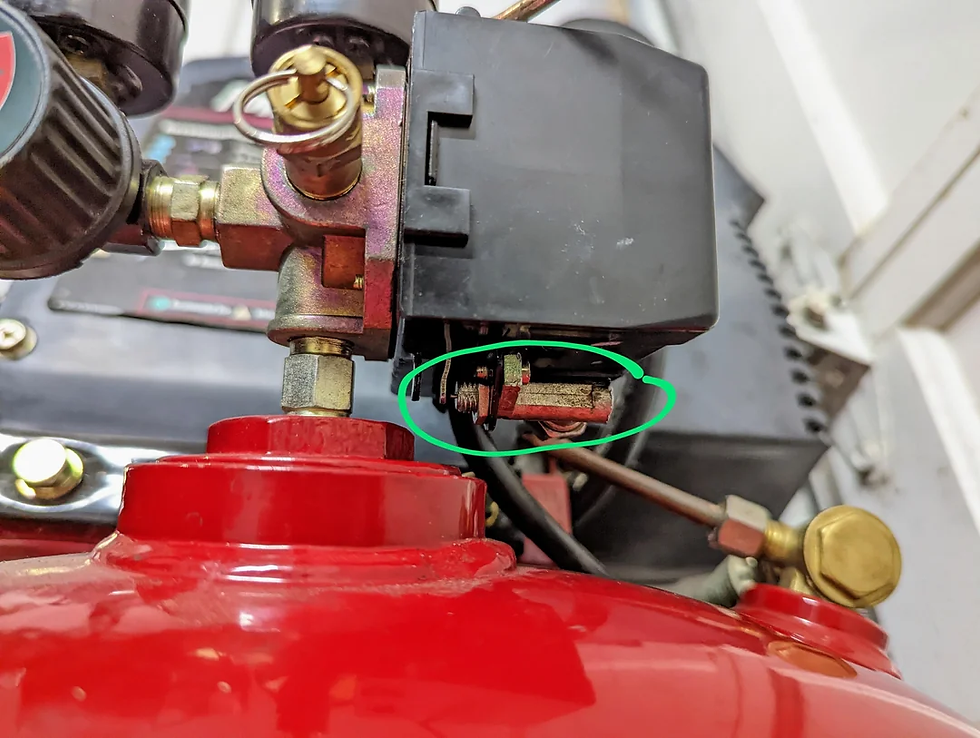
A leaking discharge valve allows compressed air to flow back into the cylinder during the suction stroke.
This causes:
Reduced efficiency
Increased operating temperature
Leaky Suction Valve

A leaking suction valve allows air to return toward the suction side during compression.
This causes:
Reduced air delivery
Increased compressor running time
If the second-stage suction valve leaks significantly, pressure may build up in the intercooler.
Severe suction-valve leakage can cause the compressor to operate almost as if it were unloaded.
Factors Affecting Compressor Air Delivery
Several conditions can reduce the quantity of air delivered by a compressor.
Important causes include:
Excessive bump clearance
Defective valves
Piston-ring leakage
Restriction in the intercooler
Restricted air-intake filter
Abnormally high intake temperature
Restriction in the discharge line
A marine engineer should therefore avoid immediately assuming that a compressor itself is defective when delivery is low.
The complete suction, compression, cooling and discharge system should be investigated.
Importance of the Air Suction Filter
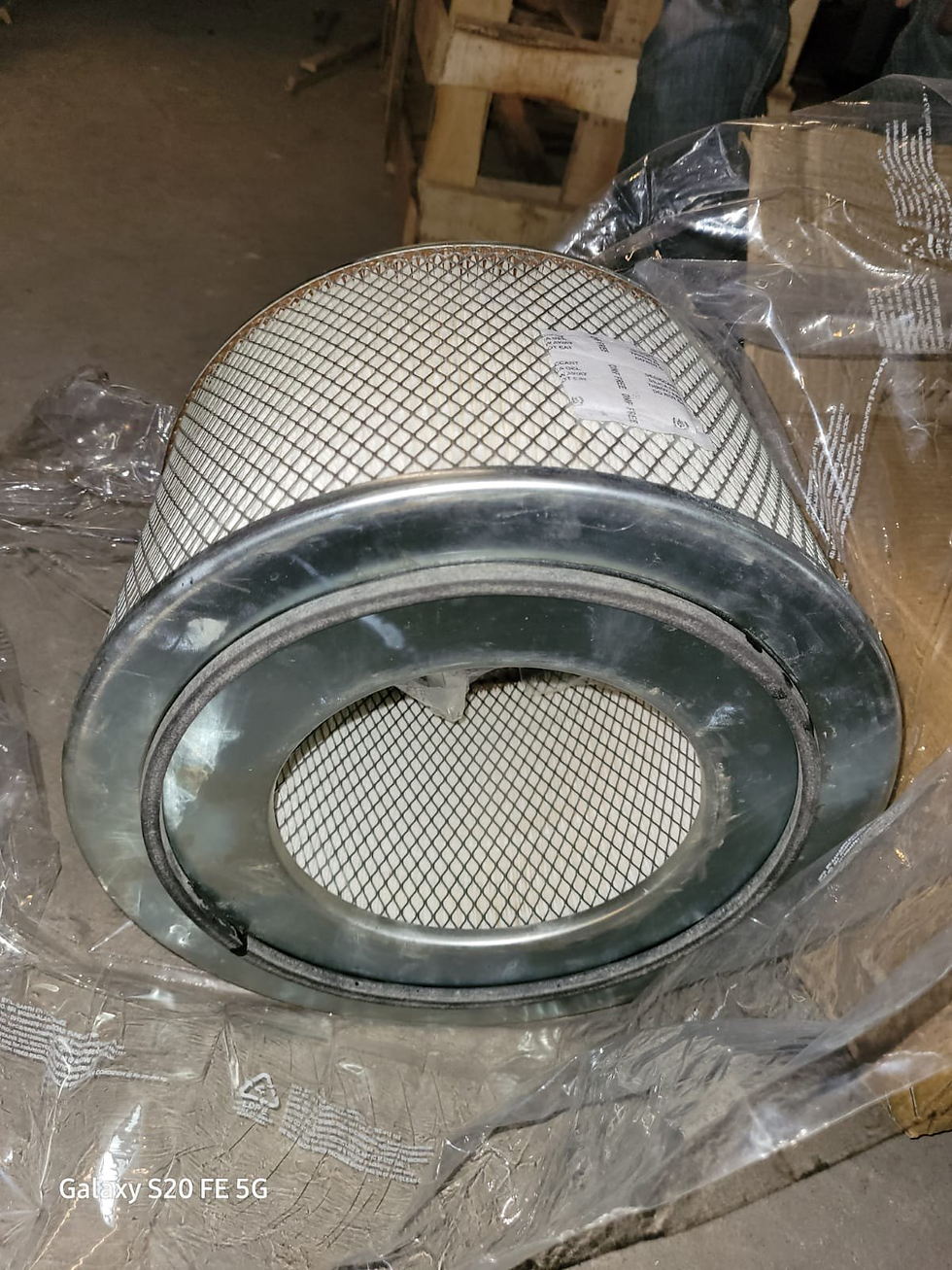
The air suction filter prevents dirt and contaminants from entering the compressor.
If the filter becomes dirty, air flow through the filter decreases.
This creates a higher pressure drop across the filter and can lead to increased delivery temperature.
In severe cases, the delivery temperature may rise to the auto-ignition temperature of lubricating oil carried over with the compressed air.
This can create an explosion hazard.
A dirty filter can also reduce compressor volumetric efficiency.
Therefore, regular inspection and cleaning of the suction filter are important parts of compressor maintenance.
Lubrication of an Air Compressor
Lubrication is essential for reducing friction and wear in moving components.
The main bearings, big-end bearings and small-end bearings can be supplied with lubricating oil by a rotary gear pump.
Oil is drawn from the crankcase sump through a strainer and delivered by the oil pump.
The oil system may include a relief valve to protect against excessive pressure.
Oil is distributed through the crankshaft passages to the main bearings, big-end bearings and connecting-rod passages leading toward the small-end bearings.
Proper lubrication is essential for:
Bearing life
Piston movement
Reduced friction
Heat removal
Reliable compressor operation
At the same time, excessive oil carryover into the compressed-air side must be avoided because oil deposits can contribute to carbon formation and create a potential fire or explosion hazard.
Safety Devices on Air Compressors
Because an air compressor handles high-pressure air and can generate high temperatures, several safety devices are provided.
Important compressor safety devices include:
Bursting disc / safety disc
Relief valve
Fusible plug
Alarms and cut-outs
Bursting Disc

A bursting disc is a pressure-relief device.
It may be fitted on the intercooler.
If a sudden abnormal pressure rise occurs, the disc bursts and provides a large opening through which pressure can be released rapidly.
This is particularly important because water is essentially incompressible. If a cooler tube fails and high-pressure air enters the water side, the resulting pressure can create a dangerous condition.
The training material notes that a bursting disc can provide immediate relief during a sudden pressure rise.
Relief Valve

Relief valves protect components against excessive pressure.
They are set to open when pressure rises above the specified safe limit.
The supplied material indicates a setting of approximately 10% above working pressure for the relevant relief arrangements.
Fusible Plug

A fusible plug provides protection against excessive temperature and external fire conditions.
The plug contains a fusible material that melts at a specified temperature.
When exposed to excessive heat, the plug melts and releases the high-pressure air, preventing the pressure vessel from becoming dangerously over-pressurized.

Fusible plugs are particularly important on air receivers because external heat from an engine-room fire can cause the temperature and pressure of the stored air to increase.
Alarms and Cut-Outs
Modern compressors incorporate protective alarms and automatic shutdown arrangements.
Examples include:
Cooling-water failure alarm
Low lubricating-oil pressure alarm and trip
High delivery-air temperature alarm
Moisture drain/unloader arrangement
The supplied material gives a maximum aftercooler outlet delivery-air temperature of approximately 93°C for the stated arrangement.
Unloader or Moisture Drain Valve

The unloader, also called the moisture drain valve, has an important role during compressor starting.
At the time of starting the compressor, the unloader should be open.
This reduces the starting torque required by the compressor and also allows accumulated moisture and oil to be cleared from the system.
Once the compressor reaches normal operation, the appropriate operating arrangement allows compression to take place.
Typical Compressor Parameters
The supplied training material gives the following example parameters:
Parameter | Typical Value |
LP discharge pressure | 4 bar |
HP discharge pressure | 30 bar |
Intercooler inlet air temperature | 130°C |
Intercooler outlet air temperature | 35°C |
Aftercooler inlet air temperature | 130°C |
Aftercooler outlet air temperature | 35°C |
These values should be treated as example/typical parameters for the compressor arrangement described, rather than universal values for every ship or compressor.
Air Receiver or Air Bottle

The compressed air produced by the compressor is stored in an air receiver, commonly called an air bottle in marine applications.

An air receiver is a large pressure vessel that stores compressed air supplied by the main air compressor.
It performs several important functions.
1. Stores Compressed Air
It provides a reserve of compressed air for shipboard requirements.
2. Compensates for Pulsating Delivery
Reciprocating compressors produce pulsating air delivery.
The receiver helps smooth this supply and provides a reservoir for the system.
3. Helps Remove Moisture
As compressed air cools inside the receiver, moisture can condense.
The receiver therefore provides an opportunity for water to separate from the compressed air.
4. Handles Peak Demand
The receiver compensates for temporary peak demand by supplying stored compressed air when demand exceeds the immediate compressor output.
Air Receiver Mountings
A marine air receiver normally contains several important mountings and connections.

Filling Valve
Connects the main air compressor discharge line to the air receiver.
Main Engine Outlet
Supplies starting air from the receiver to the main engine.
Auxiliary Engine Outlet
Provides compressed air to auxiliary engines where required.
Auxiliary Connections
Used for other systems such as service air and safety air.
Safety Valve
Protects the air receiver against excessive pressure.
Drain Valve
Located at the bottom of the receiver to remove accumulated condensate.
Fusible Plug
Provides protection against excessive external heat and fire.
Manhole Door
Allows internal inspection and maintenance of the air bottle.
Construction of an Air Receiver
An air receiver is a pressure vessel and therefore must be manufactured according to appropriate pressure-vessel requirements.
The supplied material describes construction using high-quality low-carbon mild-steel plate, with dished or semi-ellipsoidal end plates.
The cylindrical shell and dished ends are joined by welding, with material, thickness and weld quality meeting pressure-vessel requirements and subject to certification by the relevant class surveyor.
The internal surface is protected with a suitable coating to reduce corrosion.
This coating is particularly important because corrosion can reduce the wall thickness and therefore reduce the pressure-carrying capability of the receiver.
Air Receiver Inspection
An air bottle is one of the important pressure vessels on a ship and therefore requires proper inspection.
Before inspection:
A work permit is prepared.
The air bottle is isolated.
The receiver is completely depressurized.
The receiver is drained.
Oil and water accumulated at the bottom are removed.
Mountings are removed and cleaned.
Mountings are overhauled and tested where required.
The internal surface is cleaned carefully.
Rust is removed without damaging the internal protective coating.
The surveyor is informed for inspection.
What is Checked During Air Receiver Inspection?
During inspection, particular attention is paid to:
Internal Coating
The condition of the internal protective coating is extremely important.
Corrosion can occur due to the presence of an oily-water mixture resulting from compressor carryover.
If corrosion causes wall thinning, the pressure-carrying capability of the receiver can be affected.
Where corrosion is significant, ultrasonic thickness measurement may be required.
Openings and Mountings
Openings should be inspected for wire drawing and other damage.
Drain
The drain must be checked to ensure it is completely clear.
Relief Valve
The relief valve should be inspected and pressure-tested as required.
Manhole
The manhole area should be inspected for:
Pitting
Corrosion
Wire drawing
Damage
These inspections are important because the air receiver stores compressed air at high pressure.
Actual vs Theoretical Compressor Operation
In an ideal compressor, suction and discharge valves would open and close instantaneously.
In an actual compressor, this does not happen.
The valves have mechanical inertia, and there are flow restrictions through the valves and piping.
Consequently, pressure losses occur during suction and discharge.
The actual indicator diagram therefore differs from the theoretical indicator diagram.
During discharge, delayed valve opening means compression can continue beyond the theoretical discharge point.
Similarly, during suction, the inlet valve does not open instantaneously, resulting in intake depression.
These effects increase the actual work required by the compressor.
For efficient operation, the actual compressor cycle should be as close as reasonably possible to the theoretical cycle.
This requires:
Efficient valve operation
Low valve inertia
Minimum throttling
Clean air passages
Proper piping design
Minimum friction losses
Common Air Compressor Problems and Their Causes
A marine engineer should be able to identify symptoms and investigate their possible causes.
Low Air Delivery
Possible causes include:
Dirty suction filter
Leaking suction valve
Leaking discharge valve
Excessive bump clearance
Piston-ring leakage
Intercooler restriction
Discharge-line restriction
High suction-air temperature
High Delivery Temperature
Possible causes include:
Dirty suction filter
Poor cooling
Valve leakage
Carbon deposits
Restricted air passage
Insufficient cooling-water flow
Excessive Running Time
The compressor may run for longer periods if:
Air leakage exists in the system
Compressor valves are leaking
Piston rings are worn
Bump clearance is excessive
Air demand is abnormally high
Discharge piping is restricted
High Intercooler Pressure
A leaking second-stage suction valve can cause abnormally high pressure in the intercooler.
Why Air Compressor Maintenance is Critical

Air compressors operate under a combination of:
High pressure
Elevated temperature
Continuous mechanical movement
Lubrication requirements
Cooling-water requirements
Valve loading
Small defects can therefore develop into major failures.
Regular maintenance should focus on:
Air Filter
Keep the suction filter clean to maintain adequate airflow.
Compressor Valves
Inspect suction and discharge valves for leakage, cracking, carbon deposits and damaged sealing surfaces.
Cooling System
Ensure adequate cooling-water circulation and clean heat-transfer surfaces.
Lubrication System
Check oil level, oil pressure, filters, strainers, pump operation and leakage.
Piston Rings
Inspect for excessive wear and leakage.
Intercooler and Aftercooler
Check for fouling, leakage and abnormal temperatures.
Safety Devices
Verify the condition and correct operation of relief valves, fusible plugs, bursting discs and alarms.
Drain System
Regularly drain accumulated water and oil from coolers and air receivers.
Why Moisture in Compressed Air is a Problem
Atmospheric air contains moisture.
When air is compressed, its temperature increases. After compression, the air is cooled in the intercooler, aftercooler and receiver.
As the air temperature falls, moisture can condense.
If this water is not drained, it can cause:
Corrosion
Poor operation of pneumatic equipment
Contamination of air systems
Damage to components
Water accumulation in air receivers
This is why moisture drains are provided in the compressor and air receiver system.
Air Compressor: A Simple Flow Diagram
The overall arrangement of a typical marine two-stage starting-air compressor can be understood as:

Main Engine / Auxiliary Engine
This arrangement allows the air to be compressed efficiently while controlling its temperature before storage.
Key Difference Between Single-Stage and Multi-Stage Compression
Feature | Single Stage | Multi Stage |
Compression | Entire pressure rise in one cylinder | Pressure rise divided between stages |
Temperature | Higher | Lower due to intercooling |
Work requirement | Higher for high pressure | Lower |
Cooling | More difficult | Easier |
Lubrication | More difficult at high temperature | Improved |
Efficiency | Lower at high pressure | Better |
Application | Lower-pressure requirements | High-pressure applications such as starting air |
Important Numbers to Remember for Marine Engineering Exams
Some useful values from the supplied training material are:
Atmospheric pressure: approximately 1 bar
Starting air: approximately 24–42 bar
Control air: approximately 7 bar
Service air: approximately 7 bar
Example LP discharge pressure: 4 bar
Example HP discharge pressure: 30 bar
Example intercooler outlet temperature: 35°C
Example aftercooler outlet temperature: 35°C
Example maximum aftercooler outlet temperature: approximately 93°C
Normal bump clearance: approximately 0.5–1% of cylinder bore or 3% of swept volumeAlways verify the actual values against the maker's manual, ship's operating instructions and applicable class/statutory requirements, because compressor designs and operating limits can differ.
Frequently Asked Questions
What is the main function of an air compressor?
Its primary function is to convert mechanical or electrical energy into pressure energy by compressing atmospheric air.
Why is compressed air used for starting marine engines?
Compressed air provides a reliable source of stored energy capable of producing the torque required to turn a large diesel engine during starting.
Why are two-stage compressors used?
Two-stage compression reduces the work required and allows the compressed air to be cooled between stages, controlling temperature and improving efficiency.
What is the function of an intercooler?
It cools the air between compression stages before the air enters the next stage.
What is the function of an aftercooler?
It cools the final compressed air after the final compression stage before it enters the downstream system or receiver.
What is bump clearance?
It is the small clearance volume between the piston and cylinder head at the end of the compression stroke.
What happens if bump clearance is excessive?
Less fresh air enters the cylinder, reducing air delivery and volumetric efficiency and increasing compressor running time.
Why is an air receiver required?
It stores compressed air, compensates for pulsating compressor delivery, helps remove moisture and supplies air during periods of peak demand.
Why is a fusible plug fitted?
It provides protection against excessive temperature and external fire conditions by releasing stored compressed air when the fusible material melts.
What happens if the suction filter becomes dirty?
Airflow is restricted, pressure drop increases and delivery temperature may rise. Severe conditions can create an oil ignition/explosion hazard.


